The Grenadier Forum
Register Now for enhanced site access.
INEOS Agents, Dealers or Commercial vendors please contact admin@theineosforum.com for a commercial account.

You now can’t use the Smartpass consumer output

Jean Mercier

GG#920
Grenadier Owner
Lifetime Supporter
Local time
8:45 AM
Joined
Sep 10, 2022
Messages
2,659
Reaction score
9,520
Location
Sint-Martens-Latem, Belgium
Relay it seems to be internal to the inverter. ??? NOt sure . But on the parts list there was no relapy .
GEts controlled by the Body COntrol module which does the switching.
will have more info once the inverter gets here .
Could well be indeed if it is build on purpose, but what is this connector for:
20230531_174453 what is this (002).jpg


I thought for the relay (inside or outside the invertor), but didn't check yet if it gets 12V when the motor is running.
 

Tinki

Grenadier Owner
Lifetime Supporter
Local time
7:45 AM
Joined
Jun 29, 2022
Messages
421
Reaction score
1,053
He
Could well be indeed if it is build on purpose, but what is this connector for:
View attachment 7832586

I thought for the relay (inside or outside the invertor), but didn't check yet if it gets 12V when the motor is running.
That connector from what i was able ton dig up is a CAN(controller area network ) bus connector that the Body control module (BCM) communicates via . It is what controls the inverter . Unclear at this point how . You can see it on my wiring pigtail that it connects there .
 

Tinki

Grenadier Owner
Lifetime Supporter
Local time
7:45 AM
Joined
Jun 29, 2022
Messages
421
Reaction score
1,053
I think if you measure the voltage should be variable or pulsed and not exceed 3.5v .
Have not taken the panel off yet myself . But i am
Pretty sure that is the case .
 

Tinki

Grenadier Owner
Lifetime Supporter
Local time
7:45 AM
Joined
Jun 29, 2022
Messages
421
Reaction score
1,053

Attachments

  • IMG_7752.jpeg
    IMG_7752.jpeg
    233 KB · Views: 31

Jean Mercier

GG#920
Grenadier Owner
Lifetime Supporter
Local time
8:45 AM
Joined
Sep 10, 2022
Messages
2,659
Reaction score
9,520
Location
Sint-Martens-Latem, Belgium
Love it when a plan comes together !!!!!! Ahahhahah .
Come on ineos just send the inverter already .
Below the voltages to expect from such a connector .
I have a digital oscilloscope, to be connected to my computer, perhaps I should use it to check, but I need the invertor to power my computer ;) :ROFLMAO:

(An extension electrical cable to my house will also work :))
 

Tinki

Grenadier Owner
Lifetime Supporter
Local time
7:45 AM
Joined
Jun 29, 2022
Messages
421
Reaction score
1,053
I have a digital oscilloscope, to be connected to my computer, perhaps I should use it to check, but I need the invertor to power my computer ;) :ROFLMAO:

(An extension electrical cable to my house will also work :))
Ohh yeah that is next level Jean !!!! Would be useful to know . Looking forward to it .
 

Jean Mercier

GG#920
Grenadier Owner
Lifetime Supporter
Local time
8:45 AM
Joined
Sep 10, 2022
Messages
2,659
Reaction score
9,520
Location
Sint-Martens-Latem, Belgium
Ohh yeah that is next level Jean !!!! Would be useful to know . Looking forward to it .
I don't promise I will do that (a lot of hassle), but perhaps. I will have to read my manual again, because it is like two years ago that I used my oscilloscope.

But certainly not now, it rains like hell, and my car sleeps outside.
 

Jean Mercier

GG#920
Grenadier Owner
Lifetime Supporter
Local time
8:45 AM
Joined
Sep 10, 2022
Messages
2,659
Reaction score
9,520
Location
Sint-Martens-Latem, Belgium
Ohh yeah that is next level Jean !!!! Would be useful to know . Looking forward to it .
OK, today was a dry day, no planned assignments. Yesterday I got my Anderson plugs and I wanted to continue the installation of my compressor. But I decided to play around with the red-blue-black connector (see my picture above).

First I used a (Chinese) multimeter with memory function. Beware, the minus sign means the upper pin is "ground", the lower is the "positive".
20231115_121347.jpg


Sampling rate was one measurement per second, I could rise it to twice per second, but that didn't make a difference in the pattern.
image002.png

So what did I see:
  1. when you leave the car long enough "at rest" you get a voltage of 1.16 Volt (see the first part of the graph).
  2. as soon as you do something, like opening a door or putting the contact on, with or without the motor running, you get an erratic voltage fluctuating mainly between 1.5V and 2.5V.
  3. and then you get sometimes huge peaks of more than 200V, but in my opinion these are "transient" errors, and no real measurements.
I started the measurement again with my digital scope. Sampling rate is 20ms, fastest sampling that t can do.
I could download the data, but to be honest, I didn't understand the format (long time I didn't use the scope).
And I had to stop my experiments, because I got a call for an unplanned assignment.
But, I have a picture of the screen:
20231115_130536.jpg

On the screen of the scope I don't have the scale, but I guess the lower points are 1.6 Volt, and the higher points around 3Volts.
When leaving the car at rest (not doing anything apart from the measurement) the "quiet" periods around 1.5 Volts are longer, but there is no definite pattern or lengths, it varies.

Conclusion:
  • I really don't know what this signal means (@Tinki : can you explain or make a guess?)
  • Next time I should read my oscilloscope manual again, because while writing this post, I see some improvement possibilities for the measurement.
 

Tinki

Grenadier Owner
Lifetime Supporter
Local time
7:45 AM
Joined
Jun 29, 2022
Messages
421
Reaction score
1,053
OK, today was a dry day, no planned assignments. Yesterday I got my Anderson plugs and I wanted to continue the installation of my compressor. But I decided to play around with the red-blue-black connector (see my picture above).

First I used a (Chinese) multimeter with memory function. Beware, the minus sign means the upper pin is "ground", the lower is the "positive".
View attachment 7832721

Sampling rate was one measurement per second, I could rise it to twice per second, but that didn't make a difference in the pattern.
View attachment 7832720
So what did I see:
  1. when you leave the car long enough "at rest" you get a voltage of 1.16 Volt (see the first part of the graph).
  2. as soon as you do something, like opening a door or putting the contact on, with or without the motor running, you get an erratic voltage fluctuating mainly between 1.5V and 2.5V.
  3. and then you get sometimes huge peaks of more than 200V, but in my opinion these are "transient" errors, and no real measurements.
I started the measurement again with my digital scope. Sampling rate is 20ms, fastest sampling that t can do.
I could download the data, but to be honest, I didn't understand the format (long time I didn't use the scope).
And I had to stop my experiments, because I got a call for an unplanned assignment.
But, I have a picture of the screen:
View attachment 7832734
On the screen of the scope I don't have the scale, but I guess the lower points are 1.6 Volt, and the higher points around 3Volts.
When leaving the car at rest (not doing anything apart from the measurement) the "quiet" periods around 1.5 Volts are longer, but there is no definite pattern or lengths, it varies.

Conclusion:
  • I really don't know what this signal means (@Tinki : can you explain or make a guess?)
  • Next time I should read my oscilloscope manual again, because while writing this post, I see some improvement possibilities for the measurement.
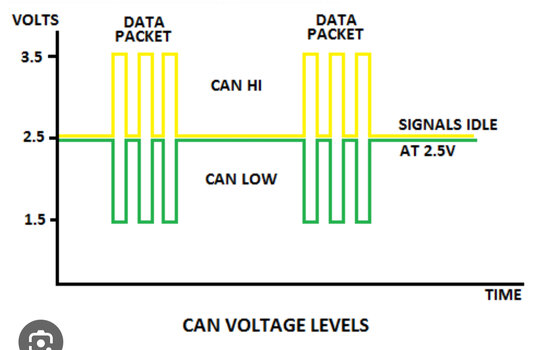
Jean my friend with out me beeing a professional in the area i will give it a stab and say this confirms my suspicion that the connector is from the CAN bus . The CAN bus will be controlling the inverter and cut it off in case of low battery voltage or other issues . If you see the picture i attached in the previous comments it is almost identical to the one from your oscilloscope (osmeloscope for the AvE (Arduino vs Evil youtube channel , check it out will not be disappointed) fans out there ) .

Thank you for taking the time and confirming . You are a truel legend ! Much appreciated.
Once i have the inverter i will do a write up . :)
 

Jean Mercier

GG#920
Grenadier Owner
Lifetime Supporter
Local time
8:45 AM
Joined
Sep 10, 2022
Messages
2,659
Reaction score
9,520
Location
Sint-Martens-Latem, Belgium
Jean my friend with out me beeing a professional in the area i will give it a stab and say this confirms my suspicion that the connector is from the CAN bus . The CAN bus will be controlling the inverter and cut it off in case of low battery voltage or other issues . If you see the picture i attached in the previous comments it is almost identical to the one from your oscilloscope (osmeloscope for the AvE (Arduino vs Evil youtube channel , check it out will not be disappointed) fans out there ) .

Thank you for taking the time and confirming . You are a truel legend ! Much appreciated.
Once i have the inverter i will do a write up . :)
Yes sure, it looks like your inserted graph.

My degree is translated in English "Master in Electronic Engineering", but I only worked two years in electronics, and it was even research on semiconductors.
Therefore my real "electronic" experience is very very limited and "old", therefore I am not a professional. But I still like to understand!

What I don't understand:
  • what is the CAN bus doing?
  • why is it fluctuating like this, while my batteries are OK?
I am really a complete novice in this :eek:
 

Tinki

Grenadier Owner
Lifetime Supporter
Local time
7:45 AM
Joined
Jun 29, 2022
Messages
421
Reaction score
1,053
Yes sure, it looks like your inserted graph.

My degree is translated in English "Master in Electronic Engineering", but I only worked two years in electronics, and it was even research on semiconductors.
Therefore my real "electronic" experience is very very limited and "old", therefore I am not a professional. But I still like to understand!

What I don't understand:
  • what is the CAN bus doing?
  • why is it fluctuating like this, while my batteries are OK?
I am really a complete novice in this :eek:
no worries my friend . The little knowledge i have is that the can bus is essentially the cars highway that helps the different modules to speak to each other .
The fluctuations are normal each fluctuation represents part of a data packet .

Happy ro be corrected by anyone who knows anything more than me ( which i am first to admit is very little ) :)
 

Jean Mercier

GG#920
Grenadier Owner
Lifetime Supporter
Local time
8:45 AM
Joined
Sep 10, 2022
Messages
2,659
Reaction score
9,520
Location
Sint-Martens-Latem, Belgium
@Tinki in the meantime I did a diagonal reading of the Wikipedia page on the CAN bus.

Your highway definition is OK, and the voltages I measured correspond to the CAN bus standard.

Therefore, I think that what I measured are signals coming from several devices in the car, and when I leave the car "at rest" unnecessary devices disconnect, therefore my frequency of peak 3V voltages disminue.

If the "INEOS" inverter needs to be connected to the CAN bus, this means it is an intelligent inverter, I mean with some kind of microprocessor inside.

Mine is a simple electronic inverter, no "computer " inside. Therefore if I want to connect it, therefore the CAN bus connector isn't useful for me.

Still a lot of guessing here, but thanks @Tinki and others for improving my knowledge, including those who already left the forum :rolleyes:
 

KDJDGrenadier

Grenadier Owner
Local time
5:45 PM
Joined
Oct 12, 2022
Messages
135
Reaction score
142
Location
Brisbane Australia
Yes sure, it looks like your inserted graph.

My degree is translated in English "Master in Electronic Engineering", but I only worked two years in electronics, and it was even research on semiconductors.
Therefore my real "electronic" experience is very very limited and "old", therefore I am not a professional. But I still like to understand!

What I don't understand:
  • what is the CAN bus doing?
  • why is it fluctuating like this, while my batteries are OK?
I am really a complete novice in this :eek:
Jean the CAN bus is a serial connection, from my understanding, that allows various electronic devices to communicate to each other. What you are seeing is probably digital communication between devices.
 

Tinki

Grenadier Owner
Lifetime Supporter
Local time
7:45 AM
Joined
Jun 29, 2022
Messages
421
Reaction score
1,053
@Tinki in the meantime I did a diagonal reading of the Wikipedia page on the CAN bus.

Your highway definition is OK, and the voltages I measured correspond to the CAN bus standard.

Therefore, I think that what I measured are signals coming from several devices in the car, and when I leave the car "at rest" unnecessary devices disconnect, therefore my frequency of peak 3V voltages disminue.

If the "INEOS" inverter needs to be connected to the CAN bus, this means it is an intelligent inverter, I mean with some kind of microprocessor inside.

Mine is a simple electronic inverter, no "computer " inside. Therefore if I want to connect it, therefore the CAN bus connector isn't useful for me.

Still a lot of guessing here, but thanks @Tinki and others for improving my knowledge, including those who already left the forum :rolleyes:
You have been the most brave man . You disassembled a brand new car to show us what is possible, if it was not for you I would had no idea of the connector .
In short its your fault , thank you for that :)

I am getting more and more excited about this !!!
 

bakepl

Grenadier Owner
Local time
5:45 PM
Joined
Feb 11, 2022
Messages
554
Reaction score
1,020
Location
Brisbane, Australia
You have been the most brave man . You disassembled a brand new car to show us what is possible, if it was not for you I would had no idea of the connector .
In short its your fault , thank you for that :)

I am getting more and more excited about this !!!
Yes, thanks again Jean et al.... made it somewhat easier for the rest of us to follow... 3 cheers... 😀
 
Back
Top Bottom