I broke a locking wheel nut a while ago and once the replacement stud arrived I drilled out the offending stud aand removed the wheel.
The front studs are press in so I had hoped i could simply knock the old one out and press the new one in. No such luck!
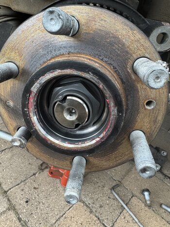
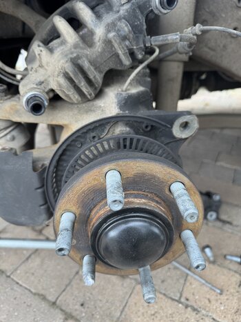
The studs hit the ABS ring on the way out so the only way to remove them is to remove the hub. I took off the tub cap and removed the retaining nut but the hub is on there solid.
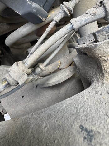
As I don't have any diagrams I can’t figure out whether it just needs more force, or whether I need to remove something else… I can’t see that there is anything else to remove, the driveshaft / axle is free to move inside the splInes in the hub, but the hub feels very tight..
Any knowledge would be greatly appreciated..
Or even better a workshop manual LOL
The front studs are press in so I had hoped i could simply knock the old one out and press the new one in. No such luck!
The studs hit the ABS ring on the way out so the only way to remove them is to remove the hub. I took off the tub cap and removed the retaining nut but the hub is on there solid.
As I don't have any diagrams I can’t figure out whether it just needs more force, or whether I need to remove something else… I can’t see that there is anything else to remove, the driveshaft / axle is free to move inside the splInes in the hub, but the hub feels very tight..
Any knowledge would be greatly appreciated..
Or even better a workshop manual LOL