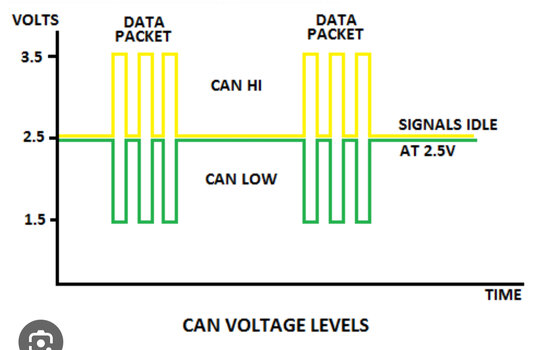
OK, today was a dry day, no planned assignments. Yesterday I got my Anderson plugs and I wanted to continue the installation of my compressor. But I decided to play around with the red-blue-black connector (see my picture above).
First I used a (Chinese) multimeter with memory function. Beware, the minus sign means the upper pin is "ground", the lower is the "positive".
View attachment 7832721
Sampling rate was one measurement per second, I could rise it to twice per second, but that didn't make a difference in the pattern.
View attachment 7832720
So what did I see:
- when you leave the car long enough "at rest" you get a voltage of 1.16 Volt (see the first part of the graph).
- as soon as you do something, like opening a door or putting the contact on, with or without the motor running, you get an erratic voltage fluctuating mainly between 1.5V and 2.5V.
- and then you get sometimes huge peaks of more than 200V, but in my opinion these are "transient" errors, and no real measurements.
I started the measurement again with my digital scope. Sampling rate is 20ms, fastest sampling that t can do.
I could download the data, but to be honest, I didn't understand the format (long time I didn't use the scope).
And I had to stop my experiments, because I got a call for an unplanned assignment.
But, I have a picture of the screen:
View attachment 7832734
On the screen of the scope I don't have the scale, but I guess the lower points are 1.6 Volt, and the higher points around 3Volts.
When leaving the car at rest (not doing anything apart from the measurement) the "quiet" periods around 1.5 Volts are longer, but there is no definite pattern or lengths, it varies.
Conclusion:
- I really don't know what this signal means (@Tinki : can you explain or make a guess?)
- Next time I should read my oscilloscope manual again, because while writing this post, I see some improvement possibilities for the measurement.


