TowPro Elite3 added to Quartermaster. Wanting to understand the electrics of the vehicle, I spent many hours of research on this forum trying to get my head around the wiring for the TowPro brake controller. Finally had some time to have a crack today, and got it installed and working properly!
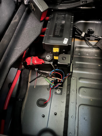
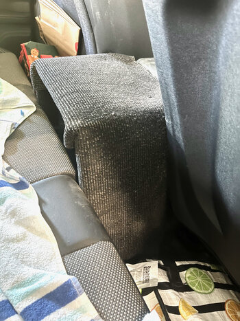
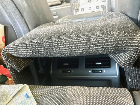
1. Install the TowPro module, and wire in under the rear seat. I installed on the back side of the bracket so I have room for my compressor. It is not really visible in the photo, but wires visible. Used 2 of the 4 wires available (power and control wires). I did not use the blue orange one, as there has been conflicting reports on weather it works, so ran my own brake wire (red). No need to connect ground, as there are plenty of ground points available in the space.
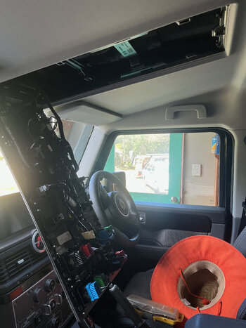
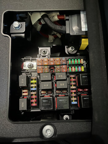
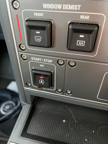
TowPro black wire - Power was taken off the Yellow / Red constant 12v, and fused to Fl13 fuse in the main fuse panel (Picture 1 and 2 ). Confirmed no power when fuse pulled. I did leave the existing circuit breaker in the line that I had already had installed in my old car. Seen wrapped in red tape picture 1.
TowPro white wire - ground. Good ground point to chases under where TowPro mounted.
TowPro Blue wire - Control wire to Grey wire. This was modified at the rear of vehicle (explain later).
TowPro Red wire ran my own to rear of vehicle from grommet in the floor, and sheathed in flex split conduit.
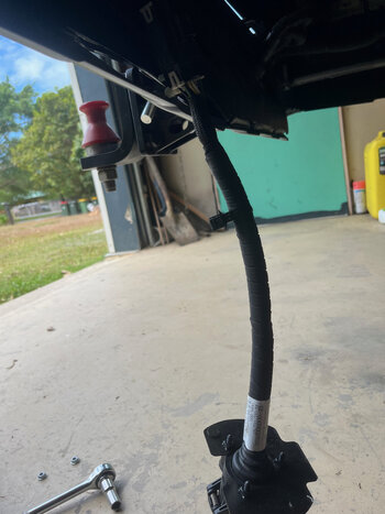
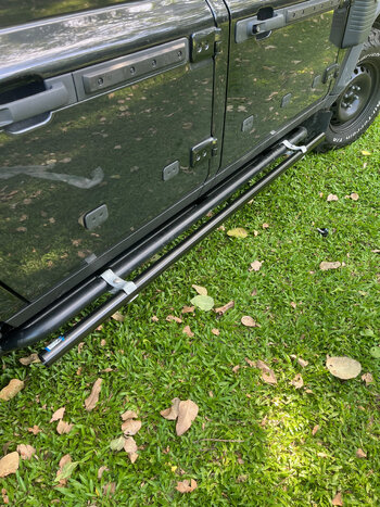
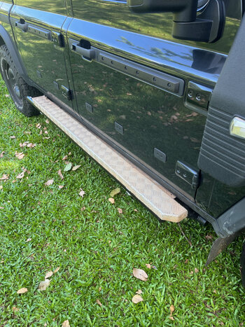
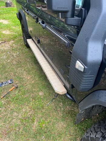
2. Rear of vehicle. There is a 400mm wiring loom extension on this Quartermaster, which makes access easy. (picture 3, and 4)
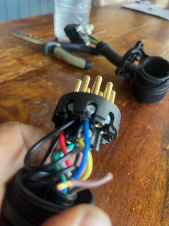
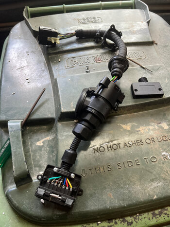
Looking at the wires coming to the connecter, the grey has no pin on the pigtail. I ended up using pin 8 reverse for the Control wire, as there is no pin 12 in the plug, and can't source in FNQ a pin puller to remove it from the 13 pin socket. I was able to use a small jewlers screwdriver to remove the purple wire in the connector of the short loom which is the Reverse light wire (pin 8 in the socket) I moved this pin to the one that correlated with the grey wire fed into, but had nothing coming off.
3. Connected the Redarc diode in line with the red wire and blue / orange of the wiring loom. Wire coming from car or signal - to orange of diode. Red wire to red feed from under the seat. Other red end to the blue orange going to socket.
4. At my 13 pin to 7 pin flat connector. Was able to take the blue wire from pin 12, and move it to pin 8. I taped and folded this brown reverse wire back up into the loom Will re instate if I ever need a reversing light on a trailer (picture 5) I do get a reverse lamp warning when going into reverse, but I know why. Goes away when I shift out of reverse.
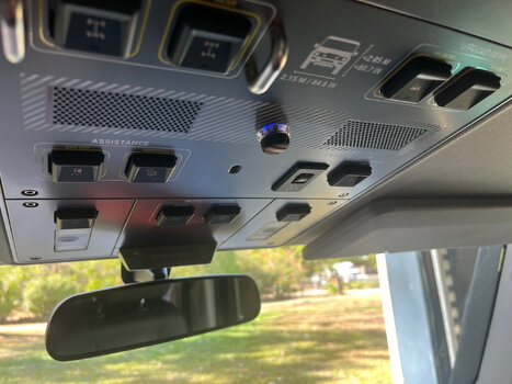
5. Running the control knob - I checked first if the system worked and calibrated before running this wire. It worked flawlessly! I then ran my extended wire from under the back seat to under the panel at the bottom of the door. I then ran it up under the rubber seal on the inside of the rear door, and up under the interior ceiling to the rear of the cab. Pulled the plastic trim piece from above the window, and exposed gap between the ceiling and roof. Undid the four screws on the upper control panel end, and was able to unsnap and swing the panel down. Found a clear spot and drilled a small hole, and used a step drill to enlarge it to fit the control knob. I fed a wire puller under the roof liner and roof to the back of the cab. fished it out, and taped the cable to it. was easy to pull through. Plugged into control knob, and closed everything up again. (Picture 6 and 7)
Happy with today's progress, and no sparks when I plugged the fuse back in.