The Grenadier Forum

Register a free account today to become a member! Once signed in, you'll be able to contribute to the community by adding your own topics, posts, and connect with other members through your own private inbox! INEOS Agents, Dealers or Commercial vendors please contact admin@theineosforum.com for a commercial account.

Build Thread Auxiliary USB charging point in auxiliary footwell power point

Re. my previous comments, it's one of the reasons why the highway patrol in Australia cracks down on passengers lounging back with their feet up on the dashboard against the windscreen. There have been cases of folks having their teeth buried in their knees and worse when the aibag has exploded while their feet were up on the dashboard :eek:
Darwin
 
IMG_4836.jpeg
 
Heads up that I tested an InReach mounted there and found that particular trim piece flapped about and made a racket on corrugations. Perhaps the handset is a little lighter?

Other issue is that the material used in that spot seems to shrug off double-sided tape a bit more readily than the dash and lower trim panels. YMMV!

We don’t have the heated seats installed so both devices (UHF handset + InReach) live in those spots in our vehicle.

Test setup below, I’ll take a pic of where we landed next time I’m in the vehicle.

IMG_0857.jpeg
 
Tot
Heads up that I tested an InReach mounted there and found that particular trim piece flapped about and made a racket on corrugations. Perhaps the handset is a little lighter?

Other issue is that the material used in that spot seems to shrug off double-sided tape a bit more readily than the dash and lower trim panels. YMMV!

We don’t have the heated seats installed so both devices (UHF handset + InReach) live in those spots in our vehicle.
solid for me. No movement whatsoever
 
Heads up that I tested an InReach mounted there and found that particular trim piece flapped about and made a racket on corrugations. Perhaps the handset is a little lighter?

Other issue is that the material used in that spot seems to shrug off double-sided tape a bit more readily than the dash and lower trim panels. YMMV!

We don’t have the heated seats installed so both devices (UHF handset + InReach) live in those spots in our vehicle.

Test setup below, I’ll take a pic of where we landed next time I’m in the vehicle.

View attachment 7829502
One question and an observation if I may:
Q. the attachment points for the UHF and ?Garmin in the vacant heated seat switch locations: Does the whole panel pop out with a trim remover or are there "real" socket screws keeping it in place?

Observation: FWIW: The "InReach" GPS device as currently shown is right in the firing line for airbag deployment: The top of the dash panel being "hinged" close to the windscreen explodes open in a clam-like action to release the airbag towards the passenger. It would most likely collect the aerial section and the top 2-3 cm of the device along the way.... potentially ripping the whole thing off its mount and propelling it towards the hapless passenger .... not pretty! Might be worth considering a different position out of the "firing line"...
 
One question and an observation if I may:
Q. the attachment points for the UHF and ?Garmin in the vacant heated seat switch locations: Does the whole panel pop out with a trim remover or are there "real" socket screws keeping it in place?
I’ve not needed to remove the panel.

The UHF is attached with the double-sided mounting tape provided by GME with their handset mounts. It seems pretty solid so I’ve not done anything further.

For the Garmin I found that the RAM temporary mount for an InReach, which ships on a diamond shaped B-sized ball base plate, when removed from the base therefore has hole centres matching the spacing of the bolts of the dash.

Screws are real, I replaced a couple with 20mm M4 bolts with rubber washers to absorb vibration and provide a bit of standoff for the mount. Yet to test it on corrugations however.

IMG_0894.jpeg

Observation: FWIW: The "InReach" GPS device as currently shown is right in the firing line for airbag deployment: The top of the dash panel being "hinged" close to the windscreen explodes open in a clam-like action to release the airbag towards the passenger. It would most likely collect the aerial section and the top 2-3 cm of the device along the way.... potentially ripping the whole thing off its mount and propelling it towards the hapless passenger .... not pretty! Might be worth considering a different position out of the "firing line"...
Yes, a colleague of mine is a former Magna restraints systems design engineer so these things are front of mind. Unfortunately I moved the mounting location to the dash before seeking his assessment. I will ask the question however once he’s in the vehicle.

That particular mount is designed for motorcycles, attached with double-sided tape and was effectively tethered by it’s cable when properly installed so it was headed for the footwell in the event of the airbag discharging. Point well made though and I would consult before rigidly fixing anything to that location.

For this reason, the RAM Tough Trak I’ve mounted on the dash top is behind the centre infotainment screen, and the Overlander is mounted on the drivers‘ side of the screen, again to ensure the rather chunky Overlander device does not conflict with airbag deployment.

IMG_0892.jpeg


The InReach needs to be in grab range of driver/passenger as it’s the grab and go device and also acts as our PLB. It works better with less obstructions to the sky so wants to be up front there somewhere. You’ll see there’s a second GME mount for a handheld/backup UHF, which I was struggling to find a home for nearby the passenger seat.


IMG_0893.jpeg


Power for the Garmin InReach is run from the centre console 12V socket.

IMG_0896.jpeg
 
Last edited:
Does the whole panel pop out with a trim remover or are there "real" socket screws keeping it in place?
@globalgregors has addressed the question about the screws. To add to this, the panel is a single unit according to a sparky in the Aus FB group:
 

Attachments

  • Screenshot_20231014-071852.png
    Screenshot_20231014-071852.png
    380.8 KB · Views: 224
@globalgregors did you remove the dash to mount that tough track or is it attached with double sided tape? Thanks.
It’s drilled and screwed to the dash itself @Bruce. I thought double-sided tape if too weak would not survive corrugations and if stong enough to stick might delaminate the surface of the dash.

I should mention that all of this has taken a beating across Oz and was rock solid. Particularly happy with the UHF mount which is very convenient to hand, first time I’ve tried the magnetic mount which is an improvement on the old slot/clip mounts.
 
Last edited:
It’s drilled and screwed to the dash itself @Bruce. I thought double-sided tape if too weak would not survive corrugations and if stong enough to stick might delaminate the surface of the dash.

I should mention that all of this has taken a beating across Oz and was rock solid. Particularly happy with the UHF mount which is very convenient to hand, first time I’ve tried the magnetic mount which is an improvement on the old slot/clip mounts.
I kinda like this install. I’ll have to think about how I could utilize it.

img_0892-jpeg.7829568
 
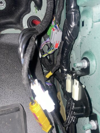
I have problems identifying the power point cables...
I do not see any cables ending there, but only cables passing through....
How did you identify the correct cables ?
 
I have problems identifying the power point cables...
I do not see any cables ending there, but only cables passing through....
How did you identify the correct cables ?
We’ve all been there - they are well hidden.

In your picture, my guess is the two cable end points you are looking for are wrapped behind the thick black loom closest to the door opening. If you undo the bracket holding the three connections (black, white and yellow),I expect the cables will be easier to see. I think you will find them just to the left of the black connector.

Good Luck
 
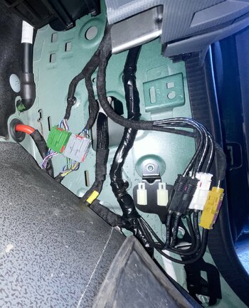
So, I removed the 3 sockets as advised, but still see no cables ending in this area.
Start to wonder if they have forgotten to pull them (early model) :unsure:

BTW... where is the repair handbook that has been promised ?
 

Attachments

  • IMG_4614.jpg
    IMG_4614.jpg
    896.5 KB · Views: 127
  • IMG_4616.jpg
    IMG_4616.jpg
    576.9 KB · Views: 121
So, I removed the 3 sockets as advised, but still see no cables ending in this area.
Start to wonder if they have forgotten to pull them (early model) :unsure:

BTW... where is the repair handbook that has been promised ?
It took me a few attempts, so I understand your frustration.

Here’s a picture of mine

20230626_115025.jpeg
 
Back
Top Bottom