The Grenadier Forum
Register Now for enhanced site access.
INEOS Agents, Dealers or Commercial vendors please contact admin@theineosforum.com for a commercial account.

Factory Subwoofer Connection Location

nodric

Grenadier Owner
Local time
3:38 AM
Joined
Feb 29, 2024
Messages
145
Reaction score
222
Location
Dallas, TX, USA
Do we know the location of the harness plug/connector when adding the JBL Nano as DIY install?

I have the aux battery but the stock head unit has zero oomph so considering adding the JLB Nano.
 

anand

Photo Contest Winner
Forum Moderator
Grenadier Owner
Lifetime Supporter
Local time
4:38 AM
Joined
Mar 12, 2023
Messages
2,992
Reaction score
4,846
Location
Maryland
It's on the passenger side of the center tunnel under the backseat, wrapped in grey-ish foam
 

DaBull

Grenadier Owner
Lifetime Supporter
Local time
1:38 AM
Joined
Dec 28, 2022
Messages
1,410
Reaction score
2,695
Location
California
It's on the passenger side of the center tunnel under the backseat, wrapped in grey-ish foam
Hi anand, Thanks for the heads up on the location of the plug/connector for adding a sub-wolfer. Is that there for those of us who did not order a sub-wolfer and is it a simple plug and play?
Anyone have photos?
DaBull
 

nodric

Grenadier Owner
Local time
3:38 AM
Joined
Feb 29, 2024
Messages
145
Reaction score
222
Location
Dallas, TX, USA
Hi anand, Thanks for the heads up on the location of the plug/connector for adding a sub-wolfer. Is that there for those of us who did not order a sub-wolfer and is it a simple plug and play?
Anyone have photos?
DaBull
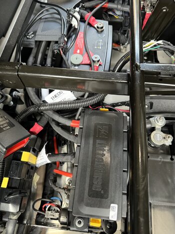
I just located the cable. It is plug and play assuming the JBL Nano is the factory fit (which is what I am led to believe). The plug discovered is the same connector for the Nano. Mine will be here in a few days and we shall soon discover.

I've attached some photos of my strip down prep. I had to fit the brake controller, hence the tools in the footwell. Takes about 10 mins to stip out the seats and covers. The PITA Torx 50 screws (that have no purpose that I can see - maybe child seats?) require a Torx angle Allen key type wrench to get the out, and even then PITA!

Despite all the issues (mostly annoying and minor) with the car, it is an insanely over-engineered car and having all this factory wiring accessible (sort of) is awesome.

I'll update this thread when I fit the Nano.
 

Attachments

  • Nano.jpg
    Nano.jpg
    266.4 KB · Views: 170
  • IMG_2894.jpg
    IMG_2894.jpg
    876.7 KB · Views: 163
  • IMG_2890.jpg
    IMG_2890.jpg
    1.1 MB · Views: 154
  • IMG_2891.jpg
    IMG_2891.jpg
    1.8 MB · Views: 144
  • IMG_2893.jpg
    IMG_2893.jpg
    1.8 MB · Views: 151

nodric

Grenadier Owner
Local time
3:38 AM
Joined
Feb 29, 2024
Messages
145
Reaction score
222
Location
Dallas, TX, USA
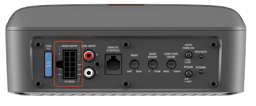
It's hard to see the pins but I did a careful comparison and they do match. You see square sockets and slightly rounded sockets. They match the layout on the factory plug so fingers crossed. This image might help. Warning - I have yet to fully validate this, but I am hopeful.
 

Attachments

  • Nano Wiring.jpg
    Nano Wiring.jpg
    397.7 KB · Views: 141

Krabby

Global Grenadier 76
Forum Moderator
Grenadier Owner
Lifetime Supporter
Local time
4:38 AM
Joined
Nov 5, 2022
Messages
5,067
Reaction score
9,713
Location
New Jersey, USA
I just located the cable. It is plug and play assuming the JBL Nano is the factory fit (which is what I am led to believe). The plug discovered is the same connector for the Nano. Mine will be here in a few days and we shall soon discover.

I've attached some photos of my strip down prep. I had to fit the brake controller, hence the tools in the footwell. Takes about 10 mins to stip out the seats and covers. The PITA Torx 50 screws (that have no purpose that I can see - maybe child seats?) require a Torx angle Allen key type wrench to get the out, and even then PITA!

Despite all the issues (mostly annoying and minor) with the car, it is an insanely over-engineered car and having all this factory wiring accessible (sort of) is awesome.

I'll update this thread when I fit the Nano.
Given that you have the dual battery setup, where do you plan to install sub?
 

nodric

Grenadier Owner
Local time
3:38 AM
Joined
Feb 29, 2024
Messages
145
Reaction score
222
Location
Dallas, TX, USA
Given that you have the dual battery setup, where do you plan to install sub?
I see a space behind the center tunnel in front of the inverter but that's not quite big enough and not sure about moving the inverter. If that fails and it probably will it can go under a seat but that would necessitate extending the cables. Not the end of the world but a minor PITA. Dimension wise it's 10-1/4" x 7-11/16" x 2-15/16"(260.0mm x 195.0mm x 74.6mm). Under the passenger seat (LHD) there is plenty of space for it That space is 8.5" wide and about 15" long. Height is no issue. Until I get it and mess with where it can go I won't know for sure, but the sound needs bass. The other spot is mounted to the plastic cover that sites in front of the auxiliary battery. It will fit there without issue but might give a real seat passenger some flappy pants/trousers. It would not foul legroom unless a short person with legs tucked right back, and since my car is predominantly a 2 person vehicle it won't matter much.

When I install it I will detail it here. I see little choice but to extend the factory harness, but that't a simple job. 8 small gauge wires. Soldering iron and some heat shrink will make that nice and tidy.

My preference is to do the rear footwell install on the battery cover. I might be able to make the factory harness reach, maybe 🤔
 

nodric

Grenadier Owner
Local time
3:38 AM
Joined
Feb 29, 2024
Messages
145
Reaction score
222
Location
Dallas, TX, USA
The installation manual for the JBL Nano.
 

Attachments

  • JBL_Basspro Nano_Quick Start Guide_EN.pdf
    1 MB · Views: 48

nodric

Grenadier Owner
Local time
3:38 AM
Joined
Feb 29, 2024
Messages
145
Reaction score
222
Location
Dallas, TX, USA
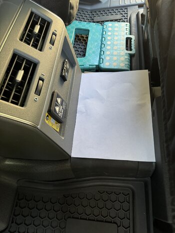
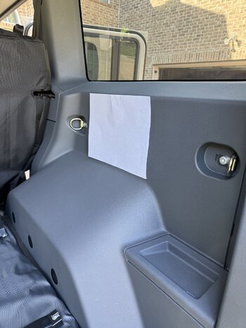
I made a paper template for the length and width and offered it up into different possible locations. Key will be vibration mitigation of course, but I'd warrant even the factory install under the seat rattles some plastic 😝

It will go just fit the passenger seat but will need a board to mount it to as it needs to be an inch or off the floor up to clear the taper of the floor shape. There is also a nice hole on the seat frame mount (non moving) that could be used to secure a fastener to anchor the install.

The outer panel in front of the auxiliary battery is a prime candidate but vibration reduction may be needed. Easy, insert acoustic foam between the panel and the battery. Can also add 1/4" or 1/2" ply (painted black) as a base attached to the plastic panel will also increase rigidity without adding bulk. If you fab you could also have a nice anodized aluminum plate instead.

I also took some photos in the rear load space with two possible locations, and showed the template on the plastic trim that sits in front of the battery. It's out currently in readiness. It's also quite substantial so not overly flimsy and with some foam between the battery and itself we may avoid having to reinforce it. My FJ sub was installed run the rear load space, so not unknown, and most kids slap them back there somewhere. Depends on future load carry needs and over landing mods.

You can even install it over the tunnel if you have no need for a middle seat passenger. It could be a thing 🤪

Anyway, loads of speculation. I am also going to install the custom ARB compressor kit that fits behind the auxiliary battery, so pulling panels and running lines will be a thing, and extending a harness isn't much more effort. I took the plastics out anyway to make getting the brake controller installed less fiddly as the harness is not overly generous in length, and getting those plastic insulators off the wires has eluded me so they get cut even shorter.
 

Attachments

  • IMG_2907.jpg
    IMG_2907.jpg
    1.2 MB · Views: 114
  • IMG_2906.jpg
    IMG_2906.jpg
    1.5 MB · Views: 94
  • IMG_2905.jpg
    IMG_2905.jpg
    1.4 MB · Views: 90
  • IMG_2904.jpg
    IMG_2904.jpg
    1.6 MB · Views: 137

landmannnn

Grenadier Owner
Local time
9:38 AM
Joined
Apr 9, 2024
Messages
577
Reaction score
892
Location
UK
Am I correct in assuming that the factory socket for the JBL sub will work with any other active subs?

If so, it would give far more choice on size/dimensions for fitting somewhere else other than the factory position.

Guessing the plug/socket is proprietary so would need an aftermarket plug or just splicing.
 

anand

Photo Contest Winner
Forum Moderator
Grenadier Owner
Lifetime Supporter
Local time
4:38 AM
Joined
Mar 12, 2023
Messages
2,992
Reaction score
4,846
Location
Maryland
Am I correct in assuming that the factory socket for the JBL sub will work with any other active subs?

If so, it would give far more choice on size/dimensions for fitting somewhere else other than the factory position.

Guessing the plug/socket is proprietary so would need an aftermarket plug or just splicing.
I believe it is a fairly standard 10 pin Molex connector; and is wired to provide sufficient power for the factory subwoofer (which is fused at 15A).

With that being said, I'm not sure if this is found on the RoW vehicles or if it is US specific. I'm 99.99% positive it does not exist on MY23 (or MY23.5) vehicles
 

Catpaw4x4

GG 4101
Grenadier Owner
Lifetime Supporter
Local time
4:38 AM
Joined
Oct 14, 2023
Messages
740
Reaction score
682
Location
Virginia, USA
I made a paper template for the length and width and offered it up into different possible locations. Key will be vibration mitigation of course, but I'd warrant even the factory install under the seat rattles some plastic 😝

It will go just fit the passenger seat but will need a board to mount it to as it needs to be an inch or off the floor up to clear the taper of the floor shape. There is also a nice hole on the seat frame mount (non moving) that could be used to secure a fastener to anchor the install.

The outer panel in front of the auxiliary battery is a prime candidate but vibration reduction may be needed. Easy, insert acoustic foam between the panel and the battery. Can also add 1/4" or 1/2" ply (painted black) as a base attached to the plastic panel will also increase rigidity without adding bulk. If you fab you could also have a nice anodized aluminum plate instead.

I also took some photos in the rear load space with two possible locations, and showed the template on the plastic trim that sits in front of the battery. It's out currently in readiness. It's also quite substantial so not overly flimsy and with some foam between the battery and itself we may avoid having to reinforce it. My FJ sub was installed run the rear load space, so not unknown, and most kids slap them back there somewhere. Depends on future load carry needs and over landing mods.

You can even install it over the tunnel if you have no need for a middle seat passenger. It could be a thing 🤪

Anyway, loads of speculation. I am also going to install the custom ARB compressor kit that fits behind the auxiliary battery, so pulling panels and running lines will be a thing, and extending a harness isn't much more effort. I took the plastics out anyway to make getting the brake controller installed less fiddly as the harness is not overly generous in length, and getting those plastic insulators off the wires has eluded me so they get cut even shorter.
Love the step stool!! Have one in purple 😅 😅
 

nodric

Grenadier Owner
Local time
3:38 AM
Joined
Feb 29, 2024
Messages
145
Reaction score
222
Location
Dallas, TX, USA
OK so I did the install today. Here are some photos and some details that people might find useful.

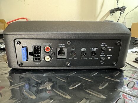
First, it is a great quality sub and is solid metal. The base is a heatsink so that also made me consider where to mount it to allow some heat dissipation.

I considered under the passenger seat but to do that well would mean moving the seat and making something to mount it with.

I scratched the idea of mounting on the outside of the plastic trim in the rear passenger footwell. Mainly as the plastic is flimsy and the unit heavy and bass causes rattles. It also would be a real fudge to stop it fouling the floor mats and it would get kick by kids (I don't have any young ones) and others. It may also have got wet and dirt kicked at it.

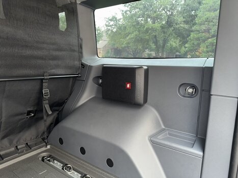
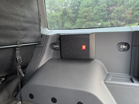
In the end I went with the rear install. Let me say it sounds amazing! Great sub and gives the audio system all the missing kick that was missing.

Also, the stock harness is so short that installing it anywhere means extending it, so I just thought 3 meters is as easy as 6 inches (confusing isn't it) so I just went for the best option in my opinion.

The sub was $185 from an eBay seller, and arrived as new perfect stock.

The side panel is a beast to get out, but it is all pop off connectors. I also added some foam (cut from the sub packaging) behind in two places just to give some sound baffling and anti vibration. The panel has some attached but it's super thin. This panel is also very solid and is fitted very tight and buts up against the metalwork under the rear window. All this means I have no vibration or reverberation other than that expected and desired.

I used the JBL supplied connector and short wiring harness. Note: Ineos have 8 wires in their harness. JBL combined the pos and neg leads using a 2 into 1 splice. This meant I only had to run a 6 core loom/harness to the rear. I simply twisted the Ineos wires together and soldered them to the new harness I made. Yes, I did finish it all off with conduit cover and tape. It is now all tucked away and safe and neat. Soldered spliced connections, heat shrunk, plastic cover (flexible split conduit), and then taped to prevent it coming apart.

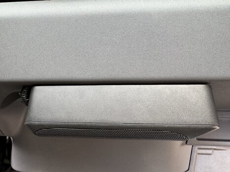
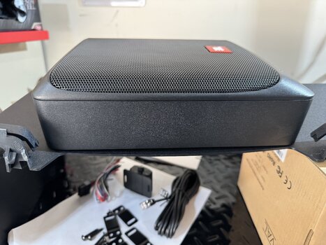
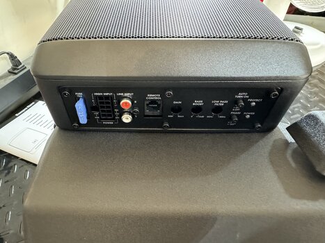
I added some pics on the bench when seeing how it might mount on the plastic battery compartment cover. It gives you some visuals of the unit.

Then the location where it went. Once removed I made a paper template and drilled 4 holes to mount the sub. It uses 4mm metric threaded screws. I used some small bolts with washers and locking washers. I also added blue thread lock to prevent anything shaking loose just in case.

You will see an image with some blue painters tape. That was just to hold the factory noise insulation in place as this was disturbed when I drilled holes. You will also see the added foam from the sub packaging materials. This stops the plastic rattling, assuming it would have anyway.

The image with the panel removed also shows the other bit of foam I added. Note, I also removed the B pillar trim where the seatbelt goes through, and loosened the trim on the B pillar that is next to the seat. I didn't take a photo that but I needed to do that to thread the wiring harness I made. It's all pretty intuitive.

The rest are images of the cable run and splice and the final result. Very impressive sound. Very clean install and probably the best worst location. Unless you need all the space for serious overloading then this will work. If you're going serious overloading then a sub ain't a priority 🤪

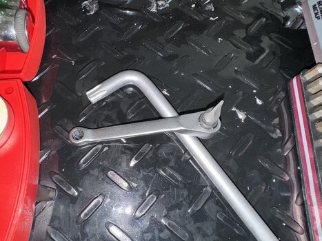
Now, dealing with those Torx 50 screws. I have an Allen style wrench but even that's a PITA. I have a T50 bit but only a Snap-On bit fits as others are too think on the spines. I found a flat blade 5/16" (about 8mm) bit also fits! Then I have a mini craftsman wrench for screwdriver bits. That is a game changer. Get one here Amazon Link.

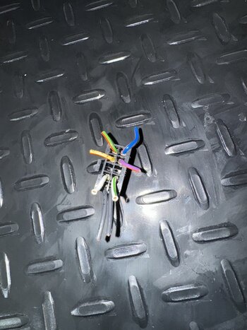
I also left you a photo of the now removed factory connector that is useful as a color code if you ever mess up.

Any questions ask away.

Did I mention it sounds awesome and is the missing oomph for the factory setup.
 

Attachments

  • IMG_2983.jpeg
    IMG_2983.jpeg
    398.3 KB · Views: 103
  • IMG_2984.jpeg
    IMG_2984.jpeg
    270.6 KB · Views: 103
  • IMG_2985.jpeg
    IMG_2985.jpeg
    351.5 KB · Views: 103
  • IMG_2986.jpeg
    IMG_2986.jpeg
    236.2 KB · Views: 104
  • IMG_2987.jpeg
    IMG_2987.jpeg
    550.4 KB · Views: 111
  • IMG_2990.jpeg
    IMG_2990.jpeg
    251.5 KB · Views: 110
  • IMG_2991.jpeg
    IMG_2991.jpeg
    264.2 KB · Views: 108
  • IMG_2992.jpg
    IMG_2992.jpg
    244.5 KB · Views: 106
  • IMG_2993.jpg
    IMG_2993.jpg
    233 KB · Views: 106
  • IMG_2982.jpeg
    IMG_2982.jpeg
    539.5 KB · Views: 103
  • IMG_2981.jpg
    IMG_2981.jpg
    468.9 KB · Views: 104
  • IMG_2967.jpeg
    IMG_2967.jpeg
    848.4 KB · Views: 98
  • IMG_2968.jpeg
    IMG_2968.jpeg
    1.3 MB · Views: 93
  • IMG_2969.jpeg
    IMG_2969.jpeg
    1.8 MB · Views: 86
  • IMG_2970.jpeg
    IMG_2970.jpeg
    1.7 MB · Views: 81
  • IMG_2971.jpg
    IMG_2971.jpg
    280.1 KB · Views: 78
  • IMG_2972.jpg
    IMG_2972.jpg
    283.8 KB · Views: 77
  • IMG_2974.jpg
    IMG_2974.jpg
    483.8 KB · Views: 77
  • IMG_2977.jpg
    IMG_2977.jpg
    318 KB · Views: 71
  • IMG_2978.jpg
    IMG_2978.jpg
    331.8 KB · Views: 72
  • IMG_3004.jpg
    IMG_3004.jpg
    768.9 KB · Views: 74
  • IMG_3005.jpg
    IMG_3005.jpg
    762 KB · Views: 73
  • IMG_3006.jpg
    IMG_3006.jpg
    737.8 KB · Views: 73
  • IMG_2989.jpeg
    IMG_2989.jpeg
    288.1 KB · Views: 69
  • IMG_2988.jpeg
    IMG_2988.jpeg
    283.8 KB · Views: 92
Last edited:

landmannnn

Grenadier Owner
Local time
9:38 AM
Joined
Apr 9, 2024
Messages
577
Reaction score
892
Location
UK
I believe it is a fairly standard 10 pin Molex connector; and is wired to provide sufficient power for the factory subwoofer (which is fused at 15A).

With that being said, I'm not sure if this is found on the RoW vehicles or if it is US specific. I'm 99.99% positive it does not exist on MY23 (or MY23.5) vehicles
In my ignorance I thought molex connectors were mostly for PC's. Useful information even if the vehicle doesn't have the factory fitted connector.
 

ScottnAZ

Grenadier Owner
Local time
2:38 AM
Joined
Dec 17, 2023
Messages
130
Reaction score
286
Location
Chandler, AZ, USA
OK so I did the install today. Here are some photos and some details that people might find useful.

First, it is a great quality sub and is solid metal. The base is a heatsink so that also made me consider where to mount it to allow some heat dissipation.

I considered under the passenger seat but to do that well would mean moving the seat and making something to mount it with.

I scratched the idea of mounting on the outside of the plastic trim in the rear passenger footwell. Mainly as the plastic is flimsy and the unit heavy and bass causes rattles. It also would be a real fudge to stop it fouling the floor mats and it would get kick by kids (I don't have any young ones) and others. It may also have got wet and dirt kicked at it.

In the end I went with the rear install. Let me say it sounds amazing! Great sub and gives the audio system all the missing kick that was missing.

Also, the stock harness is so short that installing it anywhere means extending it, so I just thought 3 meters is as easy as 6 inches (confusing isn't it) so I just went for the best option in my opinion.

The sub was $185 from an eBay seller, and arrived as new perfect stock.

The side panel is a beast to get out, but it is all pop off connectors. I also added some foam (cut from the sub packaging) behind in two places just to give some sound baffling and anti vibration. The panel has some attached but it's super thin. This panel is also very solid and is fitted very tight and buts up against the metalwork under the rear window. All this means I have no vibration or reverberation other than that expected and desired.

I used the JBL supplied connector and short wiring harness. Note: Ineos have 8 wires in their harness. JBL combined the pos and neg leads using a 2 into 1 splice. This meant I only had to run a 6 core loom/harness to the rear. I simply twisted the Ineos wires together and soldered them to the new harness I made. Yes, I did finish it all off with conduit cover and tape. It is now all tucked away and safe and neat. Soldered spliced connections, heat shrunk, plastic cover (flexible split conduit), and then taped to prevent it coming apart.

I added some pics on the bench when seeing how it might mount on the plastic battery compartment cover. It gives you some visuals of the unit.

Then the location where it went. Once removed I made a paper template and drilled 4 holes to mount the sub. It uses 4mm metric threaded screws. I used some small bolts with washers and locking washers. I also added blue thread lock to prevent anything shaking loose just in case.

You will see an image with some blue painters tape. That was just to hold the factory noise insulation in place as this was disturbed when I drilled holes. You will also see the added foam from the sub packaging materials. This stops the plastic rattling, assuming it would have anyway.

The image with the panel removed also shows the other bit of foam I added. Note, I also removed the B pillar trim where the seatbelt goes through, and loosened the trim on the B pillar that is next to the seat. I didn't take a photo that but I needed to do that to thread the wiring harness I made. It's all pretty intuitive.

The rest are images of the cable run and splice and the final result. Very impressive sound. Very clean install and probably the best worst location. Unless you need all the space for serious overloading then this will work. If you're going serious overloading then a sub ain't a priority 🤪

Now, dealing with those Torx 50 screws. I have an Allen style wrench but even that's a PITA. I have a T50 bit but only a Snap-On bit fits as others are too think on the spines. I found a flat blade 5/16" (about 8mm) bit also fits! Then I have a mini craftsman wrench for screwdriver bits. That is a game changer. Get one here Amazon Link.

I also left you a photo of the now removed factory connector that is useful as a color code if you ever mess up.

Any questions ask away.

Did I mention it sounds awesome and is the missing oomph for the factory setup.
👍 Nice write-up, thanks for documenting the leg work!
 

nodric

Grenadier Owner
Local time
3:38 AM
Joined
Feb 29, 2024
Messages
145
Reaction score
222
Location
Dallas, TX, USA
👍 Nice write-up, thanks for documenting the leg work!
Took about 5 hours, but the first hour was noodling where to install it :) And it also included time to pop to O'Relliy's and be charged excessive amounts of money for some wire/cable to make up the harness 😁

If I was to do it again I would say it is a 3-4 hours install, depending on your skills and tools, and fear factor 😉
 
Back
Top Bottom