I thought we needed a home for Ram Mount projects and have one to lead it off:

Parts list:
2 2.5"x2.5" Ram Mount Plates (I went with the 1" ball, but there is also a 1.5" version here if you prefer)
T15 and T10 torx bits
Round Needle File (I bought this cheap set from Amazon)
2 M4 40mm black screws
6 M4 20mm black screws
8 black washers (12mm outside diameter)
1 piece printer paper, pencil, scissors, scotch tape
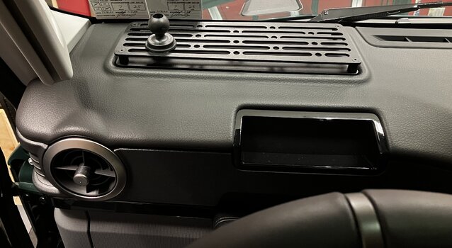
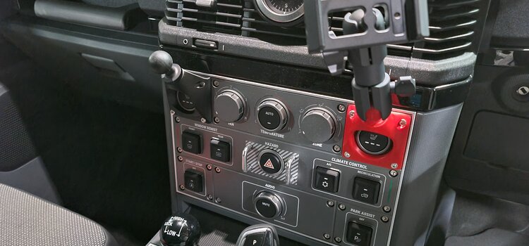
When I ordered my Grenadier without heated seats, I had in mind placing two Ram Mounts in the vacant spaces and after doing lots of dead end research and wondering if I was going to have to look into 3-D printing something, I finally found 2.5"x2.5" square Ram Mounts with a 1" ball and the four holes spaced 2" apart at gadgetmounts.com. Strangely, I had trouble finding these at rammount.com. It was only after searching the model number that I found them there. They're cheaper at gadgetmounts.com.
So, I ordered two of them from gadgetmounts.com and waited. While waiting, I removed the four screws from the console face plate using a T15 torx bit. The screws in the inner lower corners are much longer than the other three. When I received the Ram Mounts, I eagerly test fit them over the four holes and discovered the Grenadier holes are not quite spaced 2 inches apart and, as a result, I could not get the four screws back in. I did, however, figure out what type and length of screws I needed to mount the plate, taking into account the thickness of the Ram Mount. You will need two M4 40mm screws for the lower inner corner holes and six M4 20mm screws for the rest of the holes. They work perfectly and bite snugly into the holes.
To solve the problem of the Ram Mount holes not lining up correctly, I thought about widening the holes with a drill, but then decided that was too imprecise. So, I decided to do it old school with a round needle file. I picked up a cheap set from Amazon. I thought I might need the round and half round file, but I only needed the round one. After the needle files arrived, I cut out a square of printer paper, taped it over the holes, and made a pencil rubbing so I could easily lock down where the centers of the four holes were. I then cut the holes out and traced the holes on printer paper. I now had my guide:

I then lined up the holes over the back of the Ram Mount plate and, using a pencil, traced the area around the inner lower areas of the top circles and inner upper areas of the bottom circles to give me an indicator of where I needed to file down to:

With both mounts, I ended up not having to file down as far as I marked. I think maybe 200 vigorous strokes per hole was enough to get it done (TWSS). You can line up the adjusted holes on your printer paper guide to check progess as you go and eyeball whether you think you can get the four screws in. Each mount will take less than ten minutes of file work.
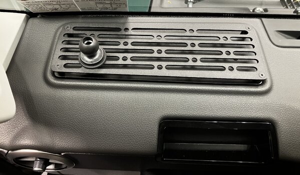
After confirming I could get all screws to bite through the widened holes into the console, I then needed to figure out what type of screws to use. Flush mount did not work (hole too big). I then tried Flanged Button Screws (ordered from Accu-Components) hoping they would cover the holes and they almost - but not quite - worked all by themselves. So, I ordered some black M4 Washers with an outside diameter of 12mm, and they were perfect. I tried regular button head screws also and they looked pretty good, but I just liked the look of the flanged screws sitting on the washers:

I only tightened the screws finger tight with a T10 torx bit and the mount is extremely solid. I did not use blue Loctite, but will if it turns out the screws start backing out. As for what I plan to mount, one will be for my Galaxy Fold 4 phone and the second may be for a Garmin device.
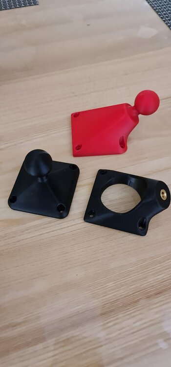
If you have done some other Ram Mount mods, please post them here (including installing any after-market options like Owl and others offer) with any install tips and pics. If you previously posted specifically about a Ram Mount project in another thread - please post a link to it here with a description. It will be great to have Ram Mount-centric stuff under one roof. I know some folks have posted about the Diamond 2-hole plate that works without having to modify the holes (and can work for those with heated seats!). If that's you, please post a link. Thanks!
Parts list:
2 2.5"x2.5" Ram Mount Plates (I went with the 1" ball, but there is also a 1.5" version here if you prefer)
T15 and T10 torx bits
Round Needle File (I bought this cheap set from Amazon)
2 M4 40mm black screws
6 M4 20mm black screws
8 black washers (12mm outside diameter)
1 piece printer paper, pencil, scissors, scotch tape
When I ordered my Grenadier without heated seats, I had in mind placing two Ram Mounts in the vacant spaces and after doing lots of dead end research and wondering if I was going to have to look into 3-D printing something, I finally found 2.5"x2.5" square Ram Mounts with a 1" ball and the four holes spaced 2" apart at gadgetmounts.com. Strangely, I had trouble finding these at rammount.com. It was only after searching the model number that I found them there. They're cheaper at gadgetmounts.com.
So, I ordered two of them from gadgetmounts.com and waited. While waiting, I removed the four screws from the console face plate using a T15 torx bit. The screws in the inner lower corners are much longer than the other three. When I received the Ram Mounts, I eagerly test fit them over the four holes and discovered the Grenadier holes are not quite spaced 2 inches apart and, as a result, I could not get the four screws back in. I did, however, figure out what type and length of screws I needed to mount the plate, taking into account the thickness of the Ram Mount. You will need two M4 40mm screws for the lower inner corner holes and six M4 20mm screws for the rest of the holes. They work perfectly and bite snugly into the holes.
To solve the problem of the Ram Mount holes not lining up correctly, I thought about widening the holes with a drill, but then decided that was too imprecise. So, I decided to do it old school with a round needle file. I picked up a cheap set from Amazon. I thought I might need the round and half round file, but I only needed the round one. After the needle files arrived, I cut out a square of printer paper, taped it over the holes, and made a pencil rubbing so I could easily lock down where the centers of the four holes were. I then cut the holes out and traced the holes on printer paper. I now had my guide:
I then lined up the holes over the back of the Ram Mount plate and, using a pencil, traced the area around the inner lower areas of the top circles and inner upper areas of the bottom circles to give me an indicator of where I needed to file down to:
With both mounts, I ended up not having to file down as far as I marked. I think maybe 200 vigorous strokes per hole was enough to get it done (TWSS). You can line up the adjusted holes on your printer paper guide to check progess as you go and eyeball whether you think you can get the four screws in. Each mount will take less than ten minutes of file work.
After confirming I could get all screws to bite through the widened holes into the console, I then needed to figure out what type of screws to use. Flush mount did not work (hole too big). I then tried Flanged Button Screws (ordered from Accu-Components) hoping they would cover the holes and they almost - but not quite - worked all by themselves. So, I ordered some black M4 Washers with an outside diameter of 12mm, and they were perfect. I tried regular button head screws also and they looked pretty good, but I just liked the look of the flanged screws sitting on the washers:
I only tightened the screws finger tight with a T10 torx bit and the mount is extremely solid. I did not use blue Loctite, but will if it turns out the screws start backing out. As for what I plan to mount, one will be for my Galaxy Fold 4 phone and the second may be for a Garmin device.
If you have done some other Ram Mount mods, please post them here (including installing any after-market options like Owl and others offer) with any install tips and pics. If you previously posted specifically about a Ram Mount project in another thread - please post a link to it here with a description. It will be great to have Ram Mount-centric stuff under one roof. I know some folks have posted about the Diamond 2-hole plate that works without having to modify the holes (and can work for those with heated seats!). If that's you, please post a link. Thanks!
Last edited:



![20250125_133727[1].jpg](https://ineosforum-data.community.forum/attachments/7843/7843502-cadebbd58835a210115a05183c2642d8.jpg?hash=COY3fNo1fT)
