The objective is to provide reliable UHF CB communications capability for a RHD vehicle in Australia.
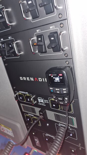
My radio of choice is a GME XRS-370C which is described as a compact hideaway 80 Channel UHF CB Radio. The reasons are that the radio is built on a metal chassis (compared to the 330C which is plastic chassis) and it has the XRS Connect speaker microphone with OLED display. It also has an amazing range of features.
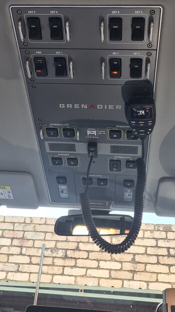
My preferred location in the vehicle is roof mounted microphone where the radio can be used from any seat in the vehicle (particularly useful with grandchildren) and does not affect night time vision while driving. It is very easy to remove the speaker microphone when the radio is not required. It is simply plugged in when going on a trip. The antenna is a matched antenna from GME – AE4018BK1, which is 6.6 DBI and 97cm.
The main body of the radio is mounted above the passenger’s feet. The speaker microphone is mounted in the centre of the roof switch panel. The antenna is bulbar mounted. The power is from the (INT 1 switch) footwell connection.
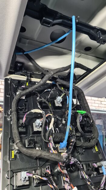
Installation commenced with removing the switch panel from the roof to fit the through-panel fitting. When complete I reinstalled the roof panel after connecting a 3m Cat 6 cable which runs down the A pillar to the passenger footwell. The radio comes with an extension cable as standard however this was not quite long enough to reach. The radio spec is for Cat 5.3 however the Cat 6 cable is a slightly higher spec and works very well.
The antenna is mounted on the bulbar and runs along to the supplied hole in the firewall. A grommet is required to protect the cable through the hole and can be fitted from the footwell side.
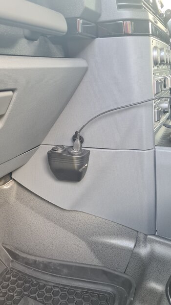
12V power is taken and supplied from the factory outlets in the passenger (left) footwell. I also used this opportunity to place a USB outlet on the tunnel cover adjacent to the footwell to provide USB outlets at a convenient place for the passenger. (Gotta keep the boss happy!)
Tricks and Tips:
Let me know if there’s any further detail that you would like.
Cheers
Pete
My radio of choice is a GME XRS-370C which is described as a compact hideaway 80 Channel UHF CB Radio. The reasons are that the radio is built on a metal chassis (compared to the 330C which is plastic chassis) and it has the XRS Connect speaker microphone with OLED display. It also has an amazing range of features.
My preferred location in the vehicle is roof mounted microphone where the radio can be used from any seat in the vehicle (particularly useful with grandchildren) and does not affect night time vision while driving. It is very easy to remove the speaker microphone when the radio is not required. It is simply plugged in when going on a trip. The antenna is a matched antenna from GME – AE4018BK1, which is 6.6 DBI and 97cm.
The main body of the radio is mounted above the passenger’s feet. The speaker microphone is mounted in the centre of the roof switch panel. The antenna is bulbar mounted. The power is from the (INT 1 switch) footwell connection.
Installation commenced with removing the switch panel from the roof to fit the through-panel fitting. When complete I reinstalled the roof panel after connecting a 3m Cat 6 cable which runs down the A pillar to the passenger footwell. The radio comes with an extension cable as standard however this was not quite long enough to reach. The radio spec is for Cat 5.3 however the Cat 6 cable is a slightly higher spec and works very well.
The antenna is mounted on the bulbar and runs along to the supplied hole in the firewall. A grommet is required to protect the cable through the hole and can be fitted from the footwell side.
12V power is taken and supplied from the factory outlets in the passenger (left) footwell. I also used this opportunity to place a USB outlet on the tunnel cover adjacent to the footwell to provide USB outlets at a convenient place for the passenger. (Gotta keep the boss happy!)
Tricks and Tips:
- The roof switch panel is plastic and not that thick. I removed all the plugs from the switches and lights, etc, to permit the panel to be taken to the work bench/table to have the square hole and microphone magnetic mount completed.
- Use blue tape to cover the switch panel in the area that you are working to protect the surface around the hole that needs cutting.
- You can mouse the Cat 6 cable down the pillar or fold back the trim and feed the cable behind which will fall into a large enough cavity.
- The radio is mounted on the metal frame in the footwell (without the mounting cradle) and the microphone mount on the switch panel with quality 3M double sided tape using isopropyl alcohol to thoroughly clean all surfaces prior.
- I made a wooden bar to make electrical connections for supply and equipment connections. Although this will likely change once other electrical equipment, like GPS, is sorted.
- I use a set of plastic auto trim removal tools to help facilitate panel removal. Besides screws the roof panel has trim clips that hold it in. They run for and aft in the centre of the back half panel. They run for and aft and side and side in the main panel. Start from the back and remove the back half panel first by removing all visible screws. Then prize down the panel from the back centre and move forward. There are two hidden screws at the rear that need removal before lowering the main panel.
- The radio and speaker microphones work and so I have found no need for an extension speaker to be fitted.
Let me know if there’s any further detail that you would like.
Cheers
Pete